A fluid mixture has been created in the Database and modeled in a single-pipe system as shown below. We can see that, when modeled, the results are suspect and we have a result of N/A for fluid phase state at the inlet and outlet of the pipe.
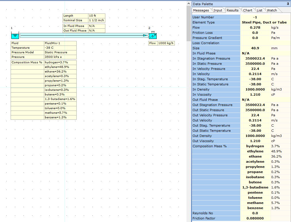
This suggests that one or more of the fluids in the mixture may be contributing to the convergence issue. The fluid mixture data (defined by mole %) is shown below.
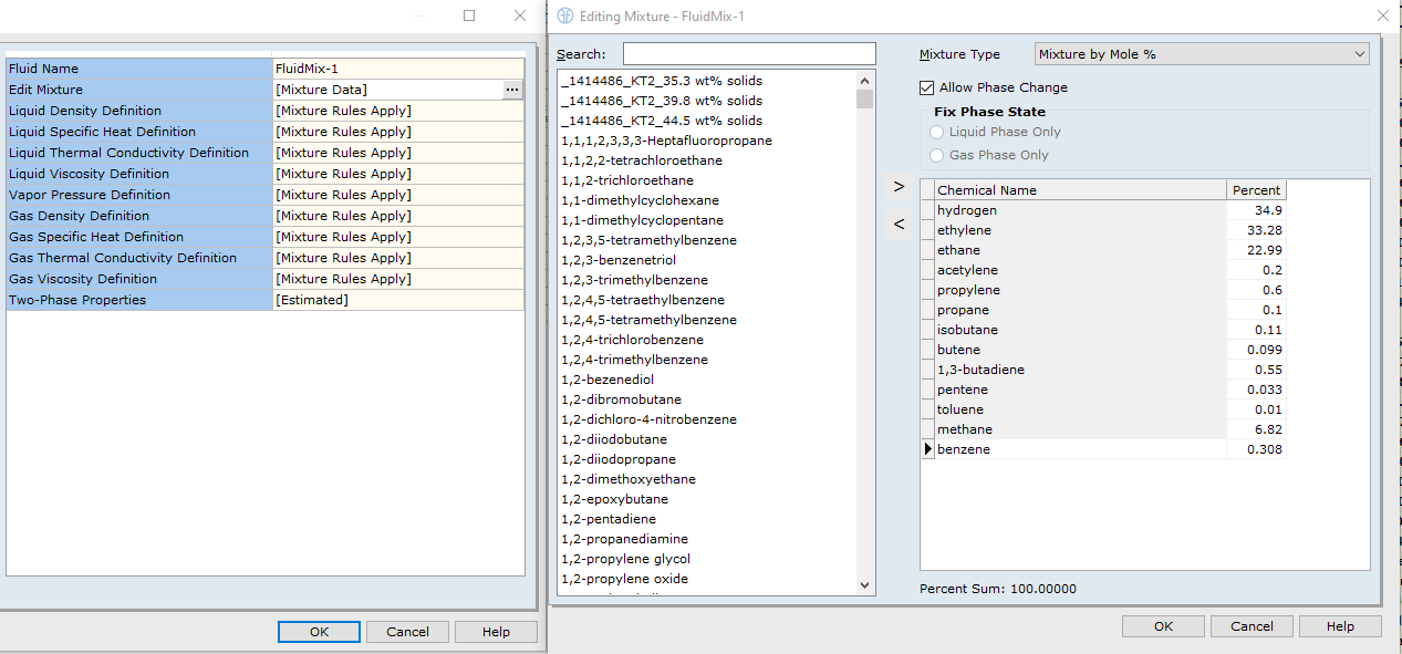
You may know from experience which fluid may be an issue however, if its not immediately obvious, what you can do is either check the physical properties of the various fluids in the database to determine which may be an issue or, you can model each of the fluids individually and mix at a central point in the system as shown below.
We created a test-case model shown below. In this test-case model, we have each of the component fluids of the mixture connecting together at a Connector node. This Connector node represents the inlet of the original pipeline. Each of the Known Flow boundary nodes is connected to the Connector node by means of a short 2 inch pipeline. A 2 inch pipe was selected since the main horizontal pipe is 1 1/2 inch in diameter and we wanted to minimize the effects of these pipes on the main system by slightly increasing the diameter. We also set each of these supply pipes to a "Status" of "Ignore Pressure Loss" again, to minimize the effects of these pipes on the main system.
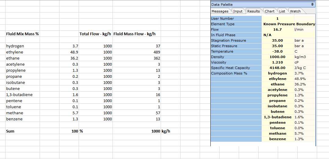
The temperature of each of the individual fluids was set to -38 degrees C which was the temperature of the fluid mixture in the original model above. The mass flow rate for each fluid had to be calculated by hand. This was simple as we know the overall system mass flow rate was 1000 kg/h. We also know the results for mass % fluid mixture details from the model in the image above.
The mass flow rate for each fluid was therefore calculated as shown below.
The test-case model then appears as shown below. We can see each individual fluid assigned to the system.
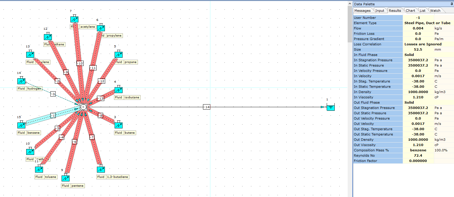
When the model is calculated, we can check the conditions for each component fluid by viewing the results for each of the supply pipes. So for instance, supply pipe node -1 for benzene shows that the fluid phase state is "Solid" and this indeed will cause a convergence issue.
You can check through the other fluids to see if there are any others with a "Solid" phase state or with unexpected results.
What you can do now is simply, set the "Status" of the relevant fluid to "Off or Closed" which is what we did in this case for benzene. The model then solved with much better results and in a 2-phase condition (see below).
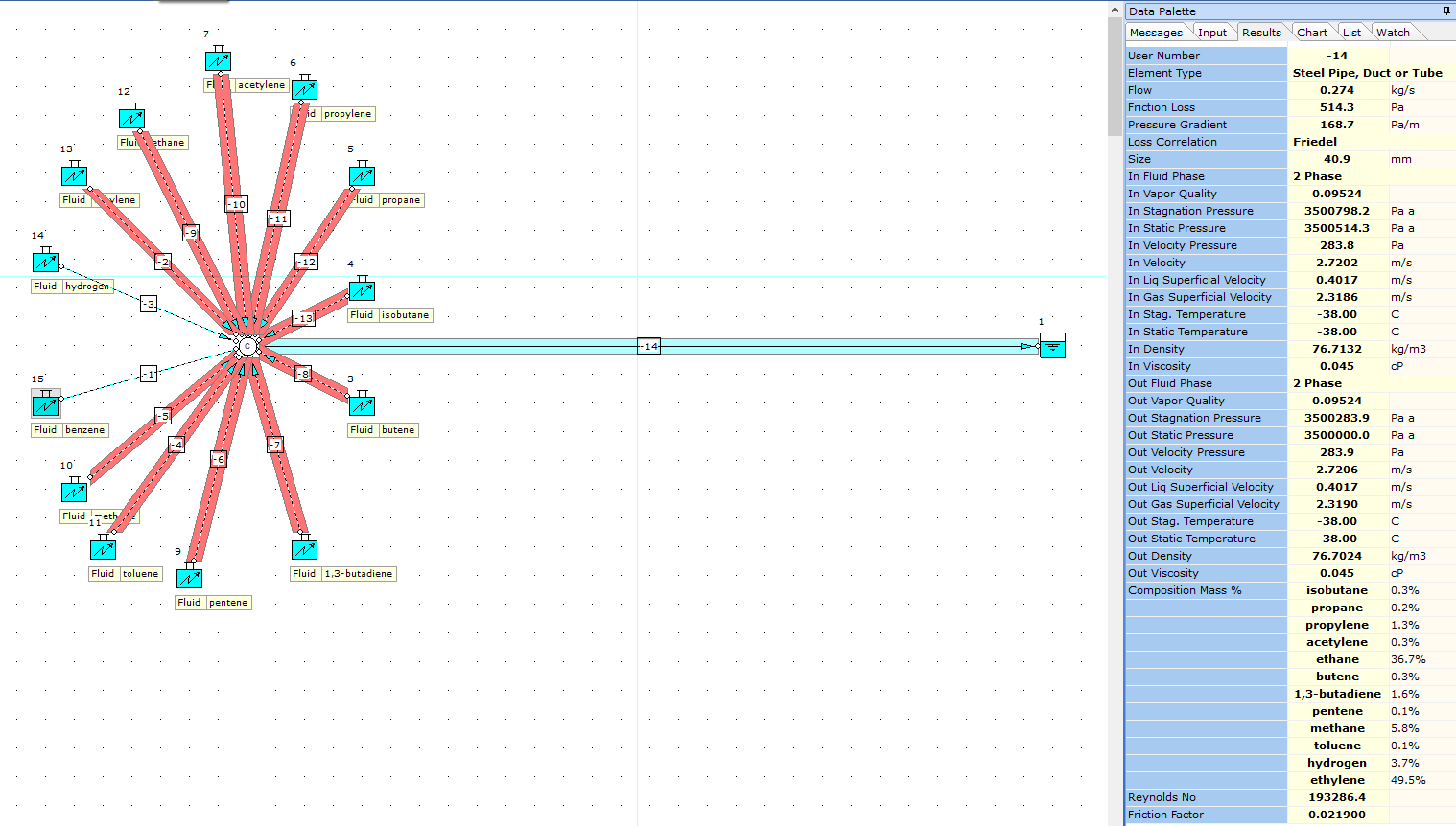
We can therefore return to our fluid mixture in the database and remove benzene. Benzene had a mole % of 0.308 in the original mixture. We therefore need to move this 0.308 % value to another one of the fluids in the mixture. We simply add this value to the fluid with the highest mole %, in this case, Hydrogen at 34.9 %.
Therefore, Hydrogen now becomes 34.9 + 0.308 = 35.208 % (by mole). The total mole % sum for the mixture is 100% as we would expect. The updated mixture data is shown below.
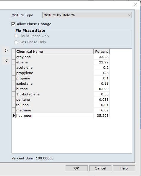
We can now model this fluid in the original system (see below), and review results to see if this has helped resolve the convergence issue. It's recommended that before you calculate the model, select:
Database | Refresh Flowsheet Data to ensure the changes we made to the fluid mixture are updated and re-initialized in the model.
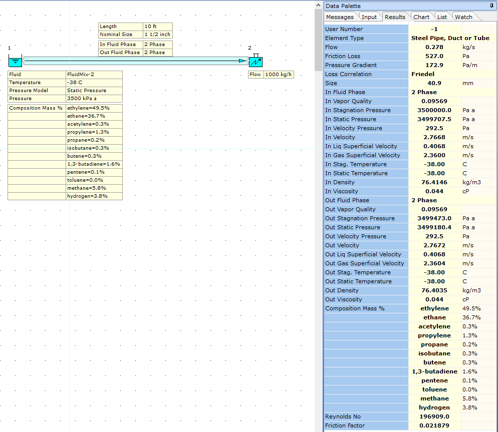
The model above now shows that the "Solid" phase problem is now resolved and we have a 2-phase system which is what was required.