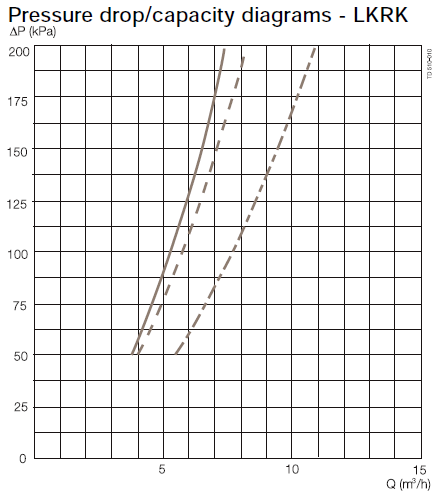
Spray Balls are used for hygienic and industrial cleaning applications and typically use a high flow rate and low pressure to clean the residue from the inside surface of tanks, milk silos etc. The pressure loss relationship of a spray ball can be modelled in FluidFlow. Figure 1 provides an illustration of a vendor spray ball capacity diagram.

Figure 1: Vendor Spray Ball Capacity Diagram.
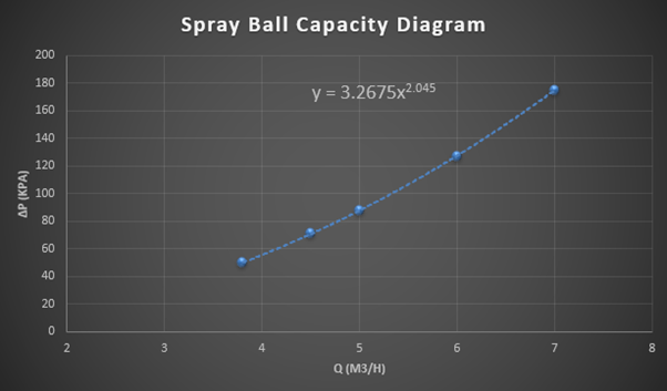
The first step to take is to read-off several data-points from the specific spray ball curve on the vendor's capacity diagram (Figure 1). Create a table of these data-points in Excel and from this data, generate a curve plot. Figure 2 provides an illustration of a Power Law curve as generated in Excel from a table of co-ordinates taken from the curve (solid line) in Figure 1.
The curve equation can then be displayed on the Chart in Excel (Figure 2) and we can then use the terms of the equation as the data-entry for the “User Defined Generic” node in FluidFlow.

Figure 2: Spray Ball Capacity Diagram Defined in Excel.
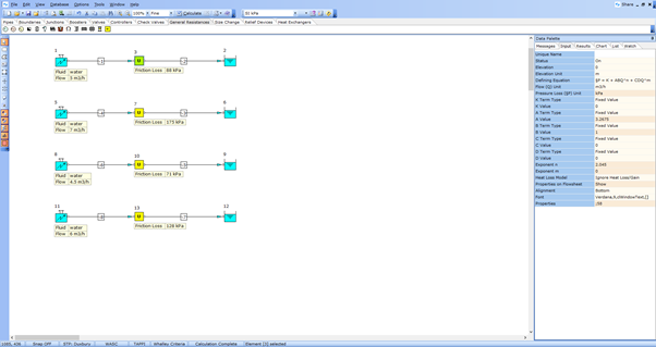
The “User Defined Generic” node allows you to define any non-standard fitting or device. Figure 3 shows how the data has been defined for this spray ball case. A number of test models using different flow rates have been created to test the accuracy of our data-entry. We can establish from the calculated pressure loss at each tested flow rate if the results compare well with the vendor curve data in Figure 1.

Figure 3: Spray Ball Modeled as a User Defined Generic Node - FluidFlow.
As we can see, the calculated pressure loss values across the "User Defined Generic" node closely match the values from the vendor curve and as such, we can be confident we have defined the values correctly and we can now model in our real system.
As noted, the “User Defined Generic” node allows you to define any non-standard fitting or device. Devices such as flame arrestors, check valves, pray balls etc have all been successfully modelled using this component.