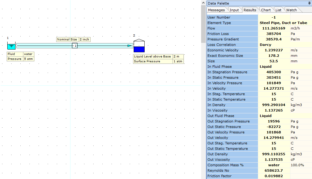
When modeling a system with a reservoir or tan node at the outlet, it's important to note that the software will calculate the values for the supply pipeline based on the defined system operating conditions etc. We then need to review the results to see if we are happy with them.
In the example case below, we have a negative value for Out Static Pressure for pipe node -1 and as such, we need to review and optimize the system operating conditions to eliminate this case.

In the model above, the pressure at the pipe outlet is the sum of the tank surface pressure 1 atm (101325 Pa) and liquid head acting on the pipe, i.e. 2.0 M. (P = rho*g*h). This of course amounts to P = 999.11 * 9.80665 * 2.0 = 19595.84416 Pa. The total pressure at the pipe outlet becomes 19595.84416 + 101325 = 120920.84 Pa a which matches the pressure results of the software for the pipe outlet. The model is then solved on this basis.
In relation to the negative value for static pressure, this has arisen due to the high flow rate in the system which yields a high velocity value and associated high velocity pressure value.
The flow rate in the 2 inch pipe is 111.26 m3/h which equates to a velocity of 14.28 m/s which may be considered a little high. The associated velocity pressure is:
Velocity Pressure = 0.5 * rho * v^2
Velocity Pressure = 0.5 * 999.11 * 14.28 * 14.28 = 101868 Pa.
As the total/stagnation pressure is approx. 120920, the static pressure at this point can be established from the stagnation pressure - velocity pressure as:
Static Pressure = 120920 - 101868 = 19053 Pa a (or -82272 Pa gauge which matches the software result).
So, based on this negative value, we need to make changes to the model to improve the results for the system. Options available include, increase pipe diameter, reduce the flow rate etc.
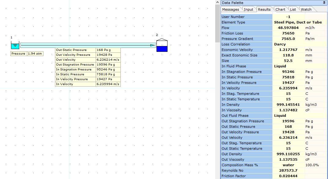
An inlet pressure of approx. 1.94 atm results in a system with a positive value for static pressure at the pipe outlet. The flow rate is 48.5 m3/h and the velocity is 6.24 m/s (see image below) which still may be considered to be high and as such, the system design may need further review. We also have a warning indicating a high velocity level for the liquid flow system.
Note, when simulating a tank, stagnation pressure should be used at the boundary as there is no velocity associated with the fluid in the tank. Stagnation pressure is equal to the sum of static pressure and velocity pressure.
