Modeling a supply pipe to a reservoir

Modeling a supply pipe to a reservoir


If you are modeling a supply pipe to a reservoir and you wish to consider the effects of the fluid in the reservoir on the calculated system, what you can do is set the fluid in the reservoir to water or air (or whatever your fluid is) and calculate on that basis.
 
We have applied this approach in the example below:
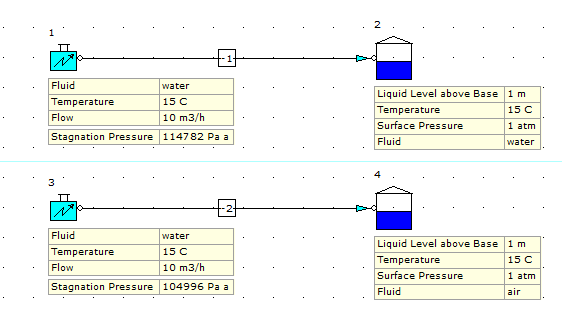
 
 
The top model has water in the receiving tank/reservoir and the second model has air. All other parameters are the same.
 
We can see in the results that the system inlet pressure takes account of the fluid in the receiving tank (takes account the density and head of the fluid in tanks 2 and 4).

    • Related Articles

    • Reservoir/Tank Node & Negative Static Pressure

      When modeling a system with a reservoir or tan node at the outlet, it's important to note that the software will calculate the values for the supply pipeline based on the defined system operating conditions etc. We then need to review the results to ...
    • Three Reservoir Problem

      This problem includes three reservoirs connected by three pipes with an additional external flow demand at the common junction of the three pipes. The highest reservoir has a water surface elevation of 100.0 M, the middle reservoir water surface ...
    • Modeling Tee Junctions

      The pressure loss at tee junctions can be modeled using any of four available relationships as follows: 1. Crane. 2. Idelchik (Default Setting). 3. Miller. 4. SAE. You can choose your preferred method from the "Tee Defined By" row as shown below. ...
    • Modeling a spray bar or sparger arrangement.

      The image below gives an overview of the approach to take when modeling a spray bar or sparger arrangement. In the image below, we can see a number of vertical 200 mm pipe sections and each pipe is defined as having an 8 mm "Inside Diameter":
    • Troubleshooting Modeling of Fluid Mixtures

      A fluid mixture has been created in the Database and modeled in a single-pipe system as shown below. We can see that, when modeled, the results are suspect and we have a result of N/A for fluid phase state at the inlet and outlet of the pipe. This ...