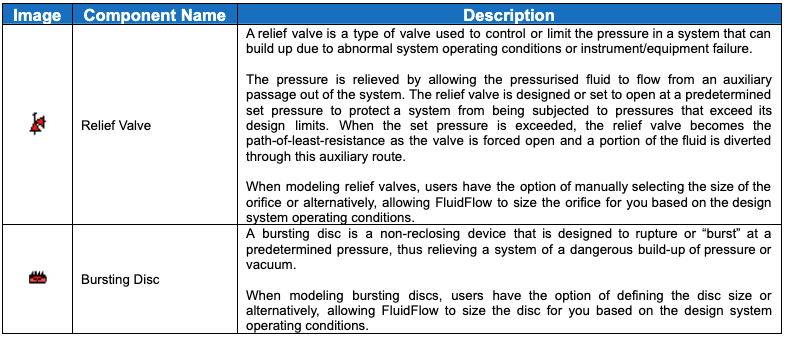
FluidFlow allows you to model two types of relief devices, relief valves, and bursting discs. Users have the option of defining the size of the valve or disc or alternatively, allowing the software to automatically size the components for you based on the system operating conditions. Users can choose from the sizing methodology applied in API (American Petroleum Institute) RP520 Part 1 and ISO 4126-1.
The table below shows the application of different relief device components available in the FluidFlow database:
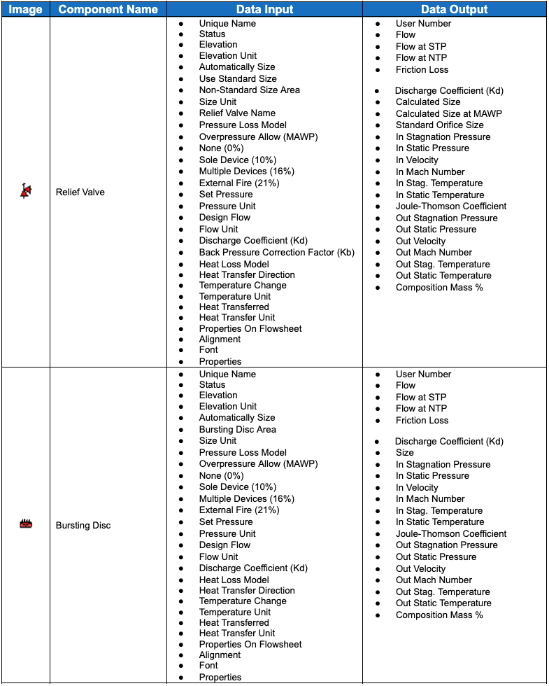
The table below shows the required data input and the output for the relief device components. Note that the results table varies depending upon the fluid phase state and the visible properties selected by the user.
Boosters Booster is a general term for any fluid machine that adds energy to a fluid and is commonly called an energy-absorbing device. Boosters are mechanical devices that transport fluid from source to destination by increasing fluid pressure. ...
General Resistances There are many types of pipe fittings that offer resistance to flow that don’t fit logically into the existing component groups. These types are available from the General Resistances of the Component palette. The resistance of ...
Boundaries Hydraulic models operate with single or multiple origins and destination points. These "points" are called boundaries within the concept of FluidFlow. Boundaries are therefore the points where the model starts and terminates. Correct ...
Size Change Size change components bring about a sudden change in velocity at the component. This can be caused by a change in the size of inlet and outlet pipes or by a sudden constriction. In FluidFlow, the thin sharp-edged orifice, thick orifice, ...