Damper node

Damper node


FluidFlow does not include a specific damper node.

Users tend to use either of the following approaches:
 
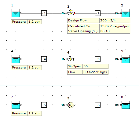
Option 1: Use a flow control valve node. This allows you to define the flow rate and the software will calculate the resultant % opening of the valve device for the given operating conditions defined. Note, the % opening is a function of the valve performance data defined in the database as well as the system operating conditions.
 
Option 2: Use a flow valve node (manual valve). This allows you to define the % opening of the valve device and the software will calculate the resultant pressure drop, flow rate etc for the given operating conditions defined. Note, the flow rate is a function of the valve performance data defined in the database as well as the system operating conditions.
 
Option 3: If you don't necessarily need to know the % opening data for the damper/device and this is something which can be established at commissioning stage, you can model the pressure loss across the damper using a Kv node or a Generic User Defined node etc. These nodes are available from the General Resistances tab of the Component Palette. You can also use a known flow boundary to define the flow rate through the damper.
 
The image below shows the three options.


    • Related Articles

    • Reservoir/Tank Node & Negative Static Pressure

      When modeling a system with a reservoir or tan node at the outlet, it's important to note that the software will calculate the values for the supply pipeline based on the defined system operating conditions etc. We then need to review the results to ...
    • Modelling hoses

      FluidFlow contains a "Flexible Smooth or Corrugated Hose" node as shown below. You can add various sizes or classifications if pipe to the database if you wish.
    • Modelling Expansion Tanks

      FluidFlow doesn't include or allow an expansion tank to be modeled in-line in a system as this would tend to be a dynamic type of scenario (fluctuating pressure/expansion) whereas in FluidFlow we tend to be solving static system conditions. Queries ...
    • Modelling vent lines

      Vent lines are usually modeled using a known pressure boundary to represent the inlet to the vent line with either a known pressure boundary or open pipe node to represent the outlet of the vent line. The only difference between these two nodes is an ...
    • How do I model a closed-loop system

      When modeling closed loop systems, we need to include a reservoir node (simply to assign a fluid, pressure and temperature) to the system. The reservoir node is modeled "in-line" and upstream of the pump node. The image below gives an example of this ...