Cooling System Modeling

Cooling System Modeling


Let's say we have heat energy of 40 kW at a piece of equipment (heat exchanger etc) and we know the pressure loss for this item is approx. 15 l/min @ 0.6 bar. We can define this condition using a Kv node as shown below.
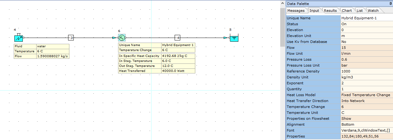


In terms of heat transfer, we know we have 40 kW of heat energy transfer at the piece of equipment (node 6) and lets say our design operating temperatures are 6 degrees C flow and 12 degrees C return, i.e. 6 degrees Delta T.

We can therefore estimate the required mass flow rate for the equipment as follows:

Q = m Cp * Delta T

m = Q / Cp * Delta T

m = 40 / 4.19268 * (12 - 6)

m = 1.590088027 kg/s.

We have therefore defined this mass flow rate for the system and a fluid flow temperature at the inlet boundary of 6 degrees C. We can see that based on the defined heat transfer value of 40 kW at node 6, the resultant outlet temperature at this node is now 12 deg C which was the basis of the design calculation above.

So we can see above, we can use a Kv to represent any device and also model heat transfer at this node (or any node).

Note, if you don't want to define a fixed flow rate in your system and wish to model tanks, you can of course use an orifice plate or flow control valve to balance the system flow rates. In the above case, we could have used a known pressure at the inlet, inserted an orifice plate and set the RO to be sized on a design flow rate of 1.590088027 kg/s.


    • Related Articles

    • Modeling Tee Junctions

      The pressure loss at tee junctions can be modeled using any of four available relationships as follows: 1. Crane. 2. Idelchik (Default Setting). 3. Miller. 4. SAE. You can choose your preferred method from the "Tee Defined By" row as shown below. ...
    • Modeling a supply pipe to a reservoir

      If you are modeling a supply pipe to a reservoir and you wish to consider the effects of the fluid in the reservoir on the calculated system, what you can do is set the fluid in the reservoir to water or air (or whatever your fluid is) and calculate ...
    • How do I model a closed-loop system

      When modeling closed loop systems, we need to include a reservoir node (simply to assign a fluid, pressure and temperature) to the system. The reservoir node is modeled "in-line" and upstream of the pump node. The image below gives an example of this ...
    • Spray Ball Modeling

      Spray Balls are used for hygienic and industrial cleaning applications and typically use a high flow rate and low pressure to clean the residue from the inside surface of tanks, milk silos etc. The pressure loss relationship of a spray ball can be ...
    • Troubleshooting Modeling of Fluid Mixtures

      A fluid mixture has been created in the Database and modeled in a single-pipe system as shown below. We can see that, when modeled, the results are suspect and we have a result of N/A for fluid phase state at the inlet and outlet of the pipe. This ...