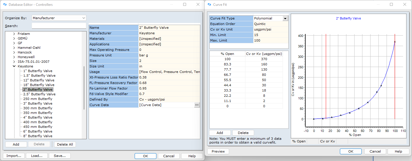
In relation to the valve position of a control valve, there's actually two layers of warning for this condition.
1. The software will enunciate a warning message if the control valve position is calculated to be below the minimum or above the maximum limit set for the valve in the Database. Let's consider the valve below. The Min Limit is 15% and the Max Limit is 100%. In this scenario, if the valve is below 15% open, we get a warning message to advise of this condition. As 100% is the fully open position, if the valve solves at 100%, we get a warning message to advise the valve is fully open. If for example the Max Limit was set to 80%, if we were to solve this valve in a system such that the % open was for example 82 %, we would receive a warning to advise that the valve position was above the Max Limit.

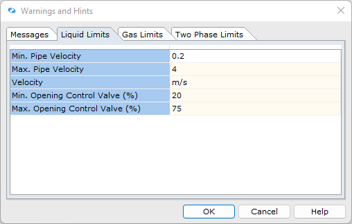
2. The second layer is based on good practice. The software includes settings for warning messages which can be located at: Options | Warnings & Hints. The image below gives an overview of these settings. You will notice that there are different tabs for different settings for Liquid, Gas and Two-Phase Limits.

In the image above, the Min Limit is 20% and the Max Limit is 75%. If the conditions described in item 1 above are such that there is no warning, there is the potential for a warning to be shown if the conditions in item 2 are not satisfied.
So for example, if we modeled a control valve in a liquid system and the valve position was 76%, based on the limits defined in the image above, we would have a warning as the valve position is above the 75% limit. This as noted is a good practice limit and depending on the system, frequency of use etc etc, you can apply engineering judgement and accept or ignore warning messages as you wish. Remember, they are shown to help users to develop efficient and elegant design solutions.