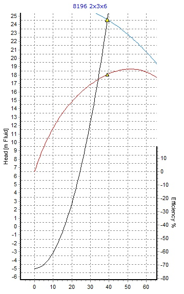
Negative Static Head:
The starting point of the system resistance curve is dependent on the characteristics of the system and although you may not expect it, the system curve can start at a negative value on the head (y) axis. This can occur in systems whereby the design inlet/outlet pressure are such that flow would occur through the system without the presence of a pump. It can also occur in systems whereby the gravity effects alone would develop flow without a pump. Obviously, the flow rates achieved in these circumstances are most likely lower than you would require from the system and as such, a pump is generally included in the system.
When a piping system exhibits the above conditions, the system resistance curve is plotted exactly as for any other case except that the static head is now negative. The system curve therefore begins at a negative value and also shows the flow rate which would be developed in the system by gravity/differential pressure alone. This is the point where the plotted system curve intercepts the flow axis.
To demonstrate this condition further, let's consider the model below.

The model on the left hand side exhibits flow through the system without the use of a pump. The flow rate achieved from gravity alone is 16 m3/h. The model on the right hand side is identical with the exception that it now includes a manufacturer's pump and the flow rate developed in the system is now 39 m3/h.
The supply tank in this design case has an elevation of 14.0 M with a liquid level of 1.0 M and a surface pressure of 1 ATM. The fluid pressure is therefore 14.0 + 1.0 = 15.0 M fluid.
The outlet point has an elevation of 10.0 M.
Therefore, the static head = 10 - 15 = - 5.0 m fluid which represents the starting point on the Head axis as shown below.

The first model illustrates that the flow occurring in the system through gravity effects is 16 m3/h. Adding the specific manufacturer's pump increased the flow rate to 39 m3/h. The above image shows that the system resistance curve intersects the flow (x) axis at 16 m3/h and 0 m head, i.e., the flow rate achieved through gravitational effects alone.
Pump Static Head:
On the subject of static head, this refers to the difference in elevation thus, the total static head of a system is the difference in elevation between the liquid levels at the discharge and suction points of the pump. The static discharge head is the difference in elevation between the discharge liquid level and the pump centreline. The static suction head on the other hand is the difference in elevation between the suction liquid level and the pump centreline. If the static suction head has a negative value because the suction liquid level is below the pump centreline, it is often referred to as static suction lift. If either the suction or discharge liquid level is under a pressure other than atmospheric, this pressure can be considered as part of the static head or separately as an addition to the static head.