The pressure loss at tee junctions can be modeled using any of four available relationships as follows:
1. Crane.
2. Idelchik (Default Setting).
3. Miller.
4. SAE.
You can choose your preferred method from the "Tee Defined By" row as shown below.

Crane
The Crane relationship is commonly used however, out of the four relationships available, it is the most simplified approach as it is based on equal-tees, i.e. doesn't consider tee junctions with different pipe-connection sizes.
Idelchik & Miller
The Idelchik and Miller relationships are more complex than the Crane method as they both consider tee junctions with different sizes of pipe connections. Both of these methods are suitable for all types of systems.
SAE
The SAE relationship considers tee junctions with different sizes of pipe connections and is considered more applicable to air or gas flow systems as the correlation was originally developed using air as the test-fluid.
Modeling Tips:
1. If you have a tee junction with different pipe connection sizes, there is no need to include a reducer to step down the pipe diameters at the point where the pipe connects to the tee. The software automatically considers changes in pipe diameter behind the scenes in the calcification.
2. It is important to set the "Branch Pipe (RED)" at each tee junction as this has an effect on the calculated results. You can view an explanation of this item by selecting the "Nomenclature" row on the Input tab of the Data Palette.
3. If you have a model with lots of tees which takes a really long time to solve or is experiencing difficulty solving, it may be due to unusual flow distribution in the system.
Warning Messages:
It's important to note that warning messages are enunciated to help you develop efficient system designs and help you decide if you need to make design changes. You don't necessarily need to eradicate all warnings and can use engineering judgment (where appropriate) and accept warning messages based on a review or interpretation of the results for the given tee junction(s) which have a warning.
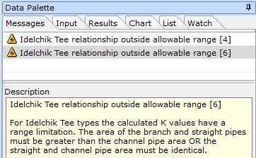
Occasionally we may receive a warning message for tee junction indicating that the Tee Relationship or K value is outside the allowable range (see example image below for an Idelchik tee).

This warning arises when we have unequal tees and refers to the possible loss of calculation accuracy in the tee junction(s) because the relationship data has been extrapolated. It is worthwhile checking on the calculated branch and straight K values in the Results to ensure these values are within an expected range (-2 to 10).
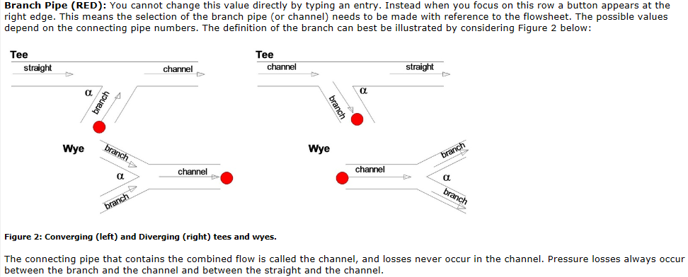
A key point to note here is that the assignment of the Branch-pipe connection (RED DOT) for each tee junction in the model should be set correctly and in accordance with the expected flow distribution. This will ensure the highest level of accuracy. You may even notice that some of the warning(s) will disappear once this has been set correctly for each tee junction. There is a further explanation on the assignment of the branch connection in the software Help file at:
Junctions | Tee and Wye Junctions | Data Entry - Tees and Wyes (see image below).

You also have the option to change the tees to another type such as Miller, Crane etc and recalculate the model. This will allow you to compare/cross-check results and validate the original results you had developed using the Idelchik method.
If you wish to review further, you can select all tees in the model and swap them to "Connector" nodes which have no associated pressure loss. Again, this allows you to compare and validate results between Connectors and tee junctions.
This warning is enunciated due to flow instability in the selected tee relationship. Internally, the software will revert to Crane type tee in order to get an approximate solution. It is however important to note that the Crane loss relationships do not take into consideration velocity changes or kinetic energy losses and as such, is not as accurate as the other available tee relationships, i.e., Idelchik or Miller.
As a means of cross-checking your model results we would suggest the following:
1.Set the status of all tees to "Ignore Pressure Loss", calculate the model and record the flow results for a selection of pipes. We will then compare the results for the selected pipes when carrying out step 2.
2.Change all tees, firstly to SAE, then Idelchik, Crane and finally, Miller. Calculate the model after each change and record the flow results for the same selection of pipes.
You will now have a clear overview of the system flow rates based on each type of tee loss relationship, including the "Ignore Pressure Loss" option. This will allow the user to establish the most accurate relationship and results.
You may find when modelling a system with Idelchik or Miller tees that you have a warning indicating that the calculated K value may be outside the allowable range. It is therefore worth checking the calculated K values to ensure they are within the accepted range, i.e., -2 to 10. You can also cross-check these values by comparing to one of the other tee loss relationships. This will help verify that the calculated K values and pressure losses are similar.
Note, you can multi-select and change all tees in the model in one action by selecting the "List" tab on the data palette followed by "Junctions" and using the scroll bar, scroll through all junctions until you display the tees. Simply left mouse click on the first tee and, holding the shift key, select the final tee. You will now see all tees have been selected on the flowsheet.
Calculation Error/Model Fails to Converge:
If you are confident in your data entry, the reason for non-convergence may be that a cross or tee is outside the experimental range used in the software. Use the List Inspector to select all tees and crosses and replace them with Connectors with No Resistance. If this is successful, then replace the Connectors one-by-one with the original junction until the culprit(s) is/are found. Usually it’s one where flow is near zero or where there is symmetrical flow into or out of the branch.
Results:
In the case of the Idelchik tees, the branch K for each tee junction is calculated behind the scenes; however, it is limited to a maximum value of 24.7 based on the experimental data and research. This is a limitation of the available experimental data and research for this method as opposed to a limitation of the software. The software applies other limits for other conditions such as minimum branch K value, K values when straight flow = zero etc, again, based on the limitations of the experimental data and research.