Pipes
A pipe is an enclosed conduit used to transport fluids. These are circular in cross-section and available in widely varying sizes, wall thicknesses, and materials. Pipes are specified in terms of their diameter and wall thickness, The wall thickness is indicated by the schedule number.
A duct is a pipe, tube, or enclosed channel for transporting gases or vapors. They are square, rectangular, or circular in cross-section, and used in air conditioning for transporting heated air and ventilation purposes.
FluidFlow contains a database of standard pipe sizes which can be used when building a network. The user can also supplement this database by adding new pipe size data for specific applications. When adding a pipe, it must be added under any of the existing FluidFlow material categories (steel, stainless steel, ductile iron, etc.).
For each piping material, there are many "nominal" pipe sizes and within the nominal size, there are many pipe classes. FluidFlow stores size information in a database of pipes, together with other piping and piping material information. This additional piping information such as material conductivity, sizing data, economic data, etc., enables the calculation of economical velocities, heat transfer, and other functions without the need for constant data entry by the user. Users have the option to directly define a pipe inner diameter on a model without the need to add a pipe to the database.
Users have the option to choose between three sizing models: Economic Velocity, By Velocity, and By Pressure Gradient. FluidFlow automatically calculates an Economic Velocity, Sizing Velocity, and Pressure Gradient, and its associated Exact Economic Size, Exact Velocity Size, and Pressure Gradient Size for each pipe in the model. The calculated velocity sizes are provided as a suggestion in order to develop an efficient system design. Note, it is down to the engineer’s discretion as to whether or not the actual pipe size needs to be changed to be more in line with that suggested by the software. Therefore, the results for velocity and size are suggested values only and do not have any effect on the overall operating conditions of the system.
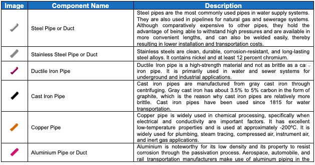
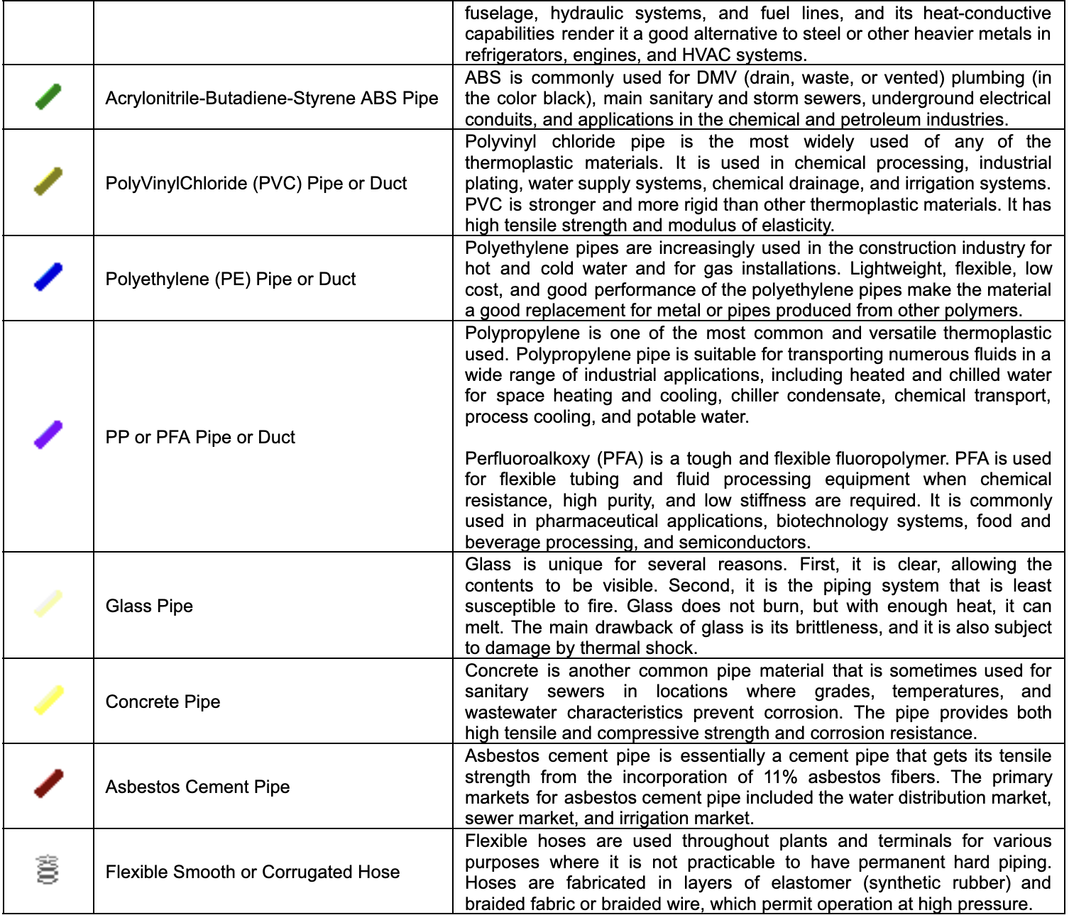
The table below shows the application of different pipe materials available in the FluidFlow database:


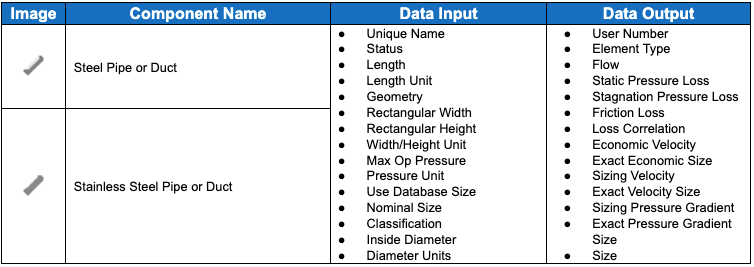
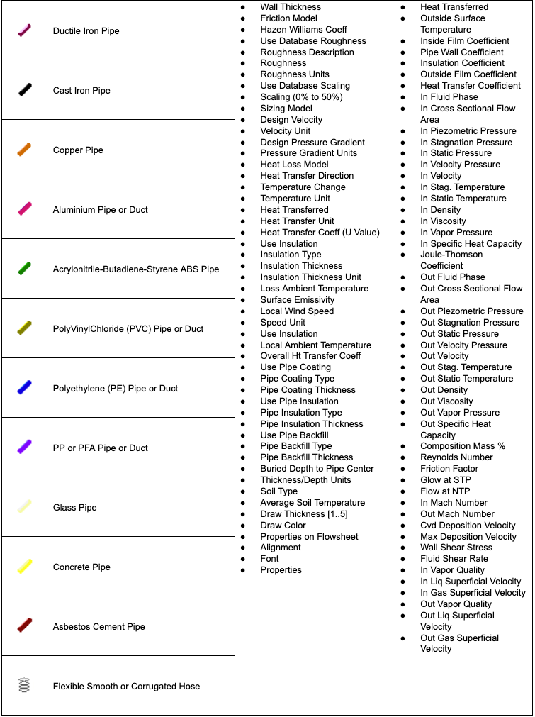
The table below shows the required data input and the output for the pipe components. Data entry for pipes is the same for all materials of construction. Note that the results table varies depending upon the fluid phase state and the visible properties selected by the user.

