Learn how to troubleshoot common FluidFlow modeling issues. Includes modeling tips, causes and solutions for warning messages, and best practices for achieving accurate and stable system simulations.
FluidFlow
TROUBLESHOOTING HANDBOOK
© Flite Software NI Ltd

1 Introduction 2
2 Modeling Tips 3
3 Model Troubleshooting 4
4 Conclusion 11
Introduction
The FluidFlow Troubleshooting Handbook is designed to assist both new and experienced users in building accurate, stable models. It provides:
- Practical modeling tips to improve accuracy and convergence.
- A guide to interpreting and resolving common warnings.
- Suggestions for avoiding over-constrained systems.
This resource is particularly valuable when encountering model convergence issues or unexpected results. If your issue is not covered here, contact support@fluidflowinfo.com with your model file, drawings, and relevant documentation for further assistance.
User Testimonials:
“I know this software well but occasionally, I forget where to fill in the inputs and then I turn to you guys to get the support. And I am really glad that your team is so fast in response. This is just wonderful and I never experienced this with any other software providers. I truly appreciate this.” – Jatinderpal Singh Mander, Process Engineer.
“Once again, I cannot begin to tell you the appreciation I have for your detailed answers and effort in my assistance in understanding FluidFlow.” – Gilbert Martinez, Mechanical Engineer.
Modeling Tips
When creating a model in FluidFlow, follow these guidelines:
- Build in Sections – Create and test smaller subsections before combining into a full model.
- Keep It Simple – Reduce complexity in flowsheets where possible.
- Keep Pipes Short – Use shorter pipes for easier navigation and visualization.
- Use “Quantity” for Multiple Bends – For liquid systems, simplify a pipe containing multiple elbows by setting the "Quantity" of the elbow element to represent several elbows. However, avoid this approach when modeling gas systems, as changes in gas density affect pressure loss calculations and reduce accuracy.
- Check Calculation Options – Ensure Calculation settings and Warnings & Hints align with your project and system requirements.
- Avoid Redundant Reducers – FluidFlow automatically detects diameter changes in tees, making additional reducers unnecessary.
- Be Cautious with Convergence Criteria – Only adjust tolerances when you have a valid engineering reason.
Model Troubleshooting
This section outlines common warning messages, possible causes, and recommended solutions.
Pipes
-
High & Low Velocity Warning
High and low velocity warnings appear based on the min and max pipe velocity limits set under Options | Warning and Hints… (see Figure 1 below). When the calculated pipeline velocity exceeds these limits, a warning message appears. You can adjust these design limits to match your specific system design parameters.
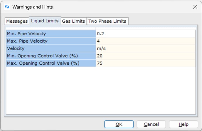
Figure 1. Liquid Limits found under Warnings and Hints.
-
Static Pressure Below Fluid Vapor Pressure or Negative
This message typically indicates a data entry issue that must be corrected to obtain accurate results.
This warning can occur for several reasons:
-
Data entry errors in node elevations. When two nodes at different elevations are connected by a pipe that's too short, this warning appears alongside Pipe Length < Elevation Difference warnings.
To resolve this issue, correct the pipe length or node elevation data and recalculate the model. The Pipe Length < Elevation Difference warnings will be eliminated, and the "Static Pressure below fluid vapor pressure or negative" warning may also disappear. If this warning persists, refer to the items below.
-
In piping flow systems, energy continuity must be maintained. If fluid velocity and velocity pressure (kinetic energy) increase significantly in a pipeline or element, the static pressure may calculate to a negative value. When this occurs, FluidFlow displays the warning Static Pressure below fluid vapor pressure or negative. This issue commonly occurs in gas systems. You may need to review your system design conditions (pipe diameters, design pressures, and flow rates) to eliminate this warning.
-
In liquid systems, this warning can appear when you try to achieve a flow rate that's too high for your system. Consider lowering your design flow rate to a value that allows the model to converge successfully and produce an acceptable solution.
-
This warning occasionally appears in large-scale systems developed exclusively with Known Pressure nodes. When modeling this way, the software automatically determines flow rates throughout the system. If you know the design flow rate at any inlet or outlet boundary, try switching one Known Pressure node to a Known Flow node. Enter the relevant flow rate and recalculate to refresh results. This often provides more accurate results and may eliminate the warning. This approach works for larger systems.
-
This warning may appear when a pipeline isn't running full-bore with fluid—for example, in vertical downstream lines with little or no back pressure where fluid runs down the pipe walls while vapor is drawn toward the centerline (column separation). This typically occurs in systems with extreme elevation differences or discontinuous elevations (see item 1).
To address this issue, first verify node elevations and pipe lengths, then recalculate the model. If the warning persists, add an orifice plate to the end of the problematic vertical pipeline. Adjust the orifice size until sufficient back pressure develops and the warning disappears.
-
This warning may occur if you've modeled a PD pump in series with a Known Flow node, which over-constrains the model. The flow rate from a PD pump depends on engineering conditions (pipe diameter, length, etc.) and pump speed—it can't be controlled by designating a Known Flow node. Instead, model this scenario with Known Pressure nodes at system boundaries and adjust the pump speed to achieve the desired flow rate.
It's important to address this warning to ensure accurate and meaningful results.
-
-
Flow Regime in Critical Region
This warning appears when pipe flow falls between the laminar and turbulent regions—specifically in the unstable transition or critical region.
You can treat this as an engineering hint that doesn't necessarily need to be eliminated. However, if you want to remove this warning, simply set the Laminar Region end equal to the Turbulent Region start (or vice versa) in Calculation Options (via Options → Calculation → Global Settings). This effectively eliminates the transition region.
-
Pipe Length < Elevation Difference
This warning appears when a pipe is too short to accommodate the elevation difference between connected nodes.
This condition typically occurs in two scenarios:
- The defined pipe length is insufficient for the elevation change.
- When adding a new node to an existing model, the user fails to change the default elevation value (zero), creating an inconsistency with the actual system geometry.
It's essential to resolve all "Pipe Length < Elevation Difference" warnings and recalculate your model. Multiple instances of this warning can hinder convergence and compromise result accuracy. Fixing this issue may require adjusting pipe lengths, node elevations, or a combination of both.
Pumps
-
Booster is Affinity Law Corrected
This warning appears when the pump speed or impeller diameter has been modified from its original value in the Input Editor. FluidFlow enables you to simulate how changes in pump speed and impeller diameter affect your piping system (if you've specified Min. and Max. speed and impeller size in the database). When modeling these changes, the software adjusts pump performance data using affinity laws.
Keep in mind that affinity laws maintain accuracy only within approximately ±20% of the original curve parameters. The software displays this warning to alert engineers when pump speed or impeller size has been altered. You must use your engineering judgment to determine if the operating point is sufficiently close to the original curve. For applications requiring greater precision, contact the pump manufacturer to obtain a performance curve specifically for your desired speed and impeller size.
-
Pump is Viscosity Law Corrected
Performance curves for centrifugal pumps are typically based on testing with clean water. When pumping fluids with viscosity of 4.3 cSt or higher, pump performance must be corrected. This correction is necessary because the viscosity of the pumped liquid significantly affects pressure losses in the impeller and diffuser channels, as well as impeller friction and internal leakage losses. As a result, performance characteristics established for water become invalid when pumping more viscous liquids like oil. Generally, the higher the liquid's viscosity compared to water, the greater the reduction in delivery capacity and head for a given power input.
The resulting de-rating of pump head and flowrate is often relatively modest. However, efficiency de-rating can be significant, potentially affecting motor size, switchgear, and cabling requirements if not properly considered.
FluidFlow performs viscosity correction based on the Hydraulic Institute Standards. This correction applies only to centrifugal pumps delivering Newtonian fluids. The automatic correction occurs only when enabled in Global Settings, which can be accessed by selecting Options | Calculation | Global Settings, or alternatively, by pressing F2 and selecting Global Settings (see Figure 2 below).
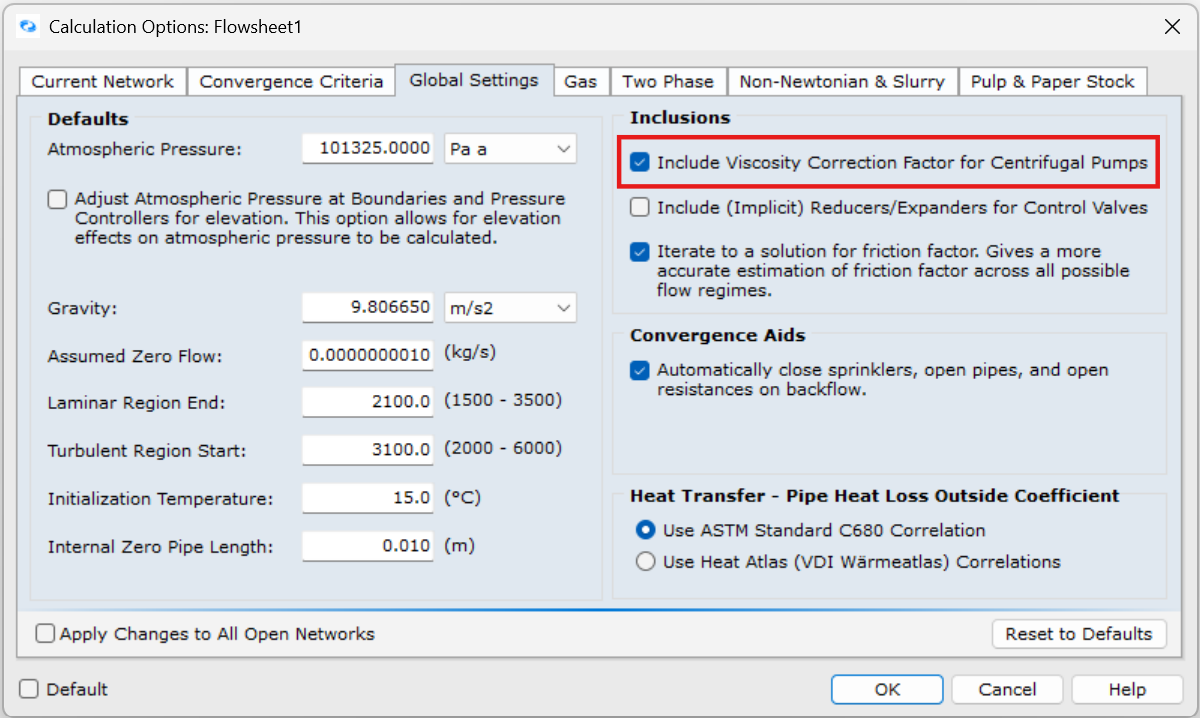
Figure 2: Global Settings – Viscosity Correction.
-
Booster is Operating in Reverse Flow Direction
This warning occurs when the pressure downstream of a pump exceeds the maximum pressure the pump can deliver. To resolve this issue, either select a larger pump, reduce the downstream pressure, increase the pump speed, or install a larger impeller to enhance the pump capacity.
Flow Control Valves
-
Calculation Error or Model Fails to Converge
Using multiple flow control valves in series can cause convergence errors because the system becomes over-constrained.
Carefully position flow controllers and set controlled flow rates to prevent these convergence issues.
Do not position flow control valves in series with Known Flow boundary nodes or centrifugal pumps that are automatically sized using design flow. This configuration creates redundant flow rate definitions that over-constrain your model.
Known or Assigned Flow
-
Calculation Error or Model Fails to Converge
Ensure that Known Flow nodes are not placed directly in series with relief valves, flow control valves, or centrifugal pumps set to Auto Size based on design flow rate. This configuration can over-constrain the system or create redundant flow definitions. Consider replacing the Known Flow node with a Known Pressure boundary node instead.
Tees
-
Flow through the Tee is Unstable
This warning occurs due to flow instability in the selected tee relationship. Internally, the software reverts to a Crane type tee to calculate an approximate solution. It's important to note that Crane loss relationships don't account for velocity changes or kinetic energy losses, making them less accurate than other available tee relationships such as Idelchik or Miller.
To cross-check your model results, we recommend the following approach:
- Set the status of all tees to "Ignore Pressure Loss," calculate the model, and record the flow results for a selection of pipes. This will serve as a baseline for comparison in step 2.
- Systematically change all tees to each available type—SAE, Idelchik, Crane, and Miller—calculating the model after each change and recording flow results for the same pipes.
This process will give you a clear overview of system flow rates based on each tee loss relationship, including the "Ignore Pressure Loss" option. This comparison will help you determine the most accurate relationship for your system.
When modeling with Idelchik or Miller tees, you may receive warnings that the calculated K value falls outside the allowable range. Verify these K values are within the accepted range (-2 to 10). You can also cross-check by comparing with other tee loss relationships to ensure the calculated K values and pressure losses are consistent.
Tip: You can quickly modify all tees in your model at once by selecting the "List" tab on the data palette, clicking "Junctions," and scrolling until you see the tees. Click on the first tee, then hold the Shift key while selecting the last tee. This will select all tees on the flowsheet simultaneously.
-
Idelchik Tee Relationship Outside Allowable Range
This warning relates to the specific combination of pipe sizes connected to the tee. The Idelchik relationships are derived empirically from a range of connection size combinations. The area of the branch and straight pipes must be greater than the channel pipe area, or the straight and channel pipe areas must be identical. The warning appears because the pipe size combination at your tees is outside this range, prompting the solver to extrapolate to determine the pressure relationships.
You can consider this warning message an engineering hint. If the branch pipe is correctly assigned using the RED DOT (as shown in the image below) for each tee junction and aligns with the expected flow distribution, and if the calculated K values fall within the range limitation (-2 to 10), the warning can be safely ignored.
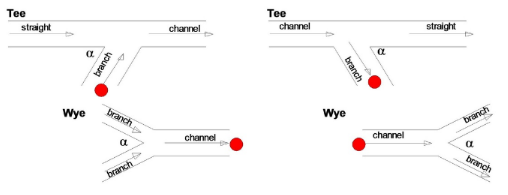
Figure 3. Converging (left) and Diverging (right) tees and wyes.
If the K value falls outside this range, try switching to Miller or Crane definitions and comparing results. Similar results across different pressure loss relationships indicate reliable calculations.
Generally, Miller and Idelchik relationships provide the most accurate results. You may encounter this warning when using either relationship since both account for different-sized pipe connections, unlike Crane. Switching to Crane will eliminate this warning, though it may affect accuracy.
Settling Slurries
-
Possibly Non-Settling Slurry
This warning is triggered based on the slurry data definition, specifically the particle size. It prompts you to verify your solids data or rheology data. If you don't have rheology data, you should obtain it to determine the fluid's physics. For fluids confirmed as non-settling, you can model them as non-Newtonian fluids.
When you've defined d50 or both d50 and d85 values, this warning indicates the slurry may be non-settling because the defined d50 particle size is less than 75 microns (0.075mm).
Similarly, if you've defined PSD (particle size distribution) values, the warning appears when the calculated d50 particle size based on your PSD is less than 75 microns (0.075mm).
The 75-micron threshold serves as a useful guide and is cited in reference literature to help define slurry flow characteristics.
You can cross-check the slurry using additional methods. Referring to the image below, you can compare your d50 particle size against the flowing velocity. This provides insight into slurry characteristics, such as homogeneous suspension.
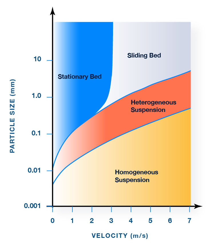
Figure 4. Flow Regime Boundaries for Settling Slurries.
An additional check using GIW data (see image below) shows how particle d50 and specific gravity together indicate slurry characteristics.
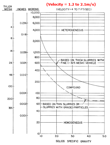
Figure 5. Slurry Flow Regime as a function of Particle Size and Specific Gravity.
Note that some literature sources indicate slurries exhibit non-settling flow characteristics when typical particle size is approximately 40 microns or smaller. In such cases, particles remain suspended within the "carrier" fluid.
Under these conditions, you may notice the "Deposition Velocity" calculation isn't displayed. This occurs because the solver has determined the slurry may be non-settling and therefore doesn't have a settling velocity.
We recommend obtaining additional information (rheology data, detailed lab analysis/report) on the solids/slurry and system before proceeding.
-
Saltation or Blockage May Occur
When designing slurry flow systems, FluidFlow will display a warning if line blockage may occur in horizontal pipes (0° angle) where slurry velocity falls below the maximum deposition velocity.
Figure 6 shows the flow regimes associated with different points on a system resistance curve.

Figure 6: Slurry Pipe Characteristic Curve.
As shown in the illustration, when flow rate/velocity decreases, the flow regime transitions from pseudo-homogeneous to heterogeneous suspension (no deposition), then to sliding bed, and finally to a stationary bed/blocked pipe.
When designing a slurry system, you should review the minimum transport velocities at all anticipated flow rates and particle concentrations. The pump suction pipe, typically having the largest diameter, often becomes the most likely location for sanding.
Slurry systems are partially self-limiting because when the effective area of pipework decreases, velocity automatically increases.
If a slurry system operates with the duty point to the left of the curve apex (deposition point), it will likely form a sliding bed, increasing pipe wear and energy costs. In worst cases, this can lead to pipe blockage. Therefore, it's best practice to design systems that operate to the right of this apex point. Engineers can optimize systems by comparing deposition velocities with actual line velocities and studying the resistance chart for each pipe.
The Cvd deposition velocity varies with slurry concentration. FluidFlow uses the maximum deposition velocity rather than the deposition velocity at the actual slurry concentration (Cvd). This approach accounts for localized concentrations that may differ from the average and for operating concentrations that change over time. Design consensus favors using maximum deposition velocity to address all possible concentration scenarios.
In vertical flows, solids don't settle at the pipe bottom. Therefore, the saltation/blockage warning doesn't trigger in vertical or minimally sloped pipes, even when velocity falls below the deposition velocity.
-
Solid Cv is Greater than the Packed Bed Voidage
A settling slurry model may generate a warning message related to packed bed voidage. The software considers the bulk density of solids defined in the solids database. This warning indicates that the defined concentration of solids exceeds what can physically fit within the pipe cross-sectional area.
Check whether your defined solids concentration is realistic for the physical space available in the pipe.
Other Common Warnings
-
Size Mismatch
This warning appears when the inside pipe diameter connecting to a valve doesn't match the valve diameter defined in the database. You can resolve this warning by either matching the pipe diameter to the valve or inserting reducers in the connecting lines.
-
Solid Phase Detected
This warning appears when a solid phase is detected, typically occurring when the fluid temperature drops below its freezing point.
To prevent this issue, implement appropriate temperature control mechanisms. For example, with heat exchangers, consider adding a bypass loop with a flow control device (or an orifice plate) to maintain minimum flow through the equipment and prevent excessive cooling. Other effective solutions include insulation, heat tracing, or adjusting operating parameters to keep fluid temperatures above freezing.
Best Practices
- Validate individual sections of your model before expanding to identify issues early.
- Use the simplest possible configuration that accurately represents your real system.
- Avoid over-constraining your model by eliminating redundant flow definitions (such as flow controllers or sized for flow pumps placed in series with known flow nodes).
- Maintain accurate pump curves and valve data in your component database.
- Cross-check results using different methods when warnings appear (e.g., comparing tee relationships).
- Review warning messages carefully as they often indicate reduced accuracy or unrealistic results.
FAQs
-
Why is my model not converging?
Common causes include:
- Over-constrained systems with conflicting boundary conditions
- Incorrect data entry (elevations, pipe lengths, or component specifications)
- Unrealistic pressure/flow relationships that create mathematical impossibilities
- Components operating outside their designed range
-
Can I ignore warnings if my model still runs?
Not recommended. Warnings indicate potential issues with your model that could lead to:
- Reduced accuracy in results
- Unrealistic system behavior predictions
- Missed design flaws that could cause operational problems
Always investigate and address warnings before finalizing your design.
-
How do I resolve high-velocity warnings?
You have several options:
- Adjust warning thresholds in
Options | Warnings & Hintsto match your specific design criteria - Increase pipe diameters in high-velocity sections
- Add parallel flow paths to distribute flow
- Review flow requirements
- Adjust warning thresholds in
Conclusion
By applying the tips and solutions in this handbook, users can build more reliable FluidFlow models, reduce troubleshooting time, and improve simulation accuracy.
Following these troubleshooting methods ensures stable, accurate FluidFlow models—saving time, improving design reliability, and preventing costly engineering errors.