FluidFlow
Applications for FluidFlow software in the Mining and Mineral Processing Industry
© Flite Software NI Ltd

1 Introduction 2
2 FluidFlow – Flowing through the entire project 3
3 Slurry Applications 4
3.1 Case 1: Tailings Booster Pump Design (Heterogeneous Settling) 4
3.2 Case 2: Copper Concentrate Pipeline (Non-Newtonian, Non-Settling) 6
4 Process Applications 8
4.1 Case 1: Dust Extraction System 8
4.2 Case 2: Cooling Circuit. 9
5 Mining Applications 10
5.1 Pit Dewatering. 10
6 Conclusion 13
7 Testimonials 14
1. Introduction
The mining and mineral processing industry provides a diverse set of challenges in the design and operation of pipelines, from complex slurry pipelines through to mine dewatering systems. The traditional requirements of reliability and availability remain key drivers in the design of any system. However the need to address capital cost, efficiency and optimisation issues continues to become more prevalent in the face of rising production costs and environmental responsibilities. Increasingly, the success of piping systems design is being assessed against all these criteria and a good designer will have considered these aspects during the design process.
FluidFlow’s powerful capabilities are used by mining and mineral processing companies to design complex fluid systems, allowing design teams to achieve a consistently high level of accuracy, and a thorough understanding of system behaviour throughout the entire design envelope.
FluidFlow in particular addresses the needs of the mining and mineral processing industry which has resulted in a strong presence globally. Customers of FluidFlow in the Mining and Mineral Processing industry include:

With specific regard to slurry systems, FluidFlow helps engineers characterize slurries, evaluate pump performance, consider pump de-rating, predict particle settling velocities, predict likelihood of blockage, predict flows and pressures, estimate solids delivered in the slurry etc. The software equips the engineer with all the tools required to successfully develop efficient slurry flow systems.
This document will detail slurry systems as well as applications within the mining and mineral processing industry where FluidFlow has been used successfully and continues to promote innovation.
2. FluidFlow – Flowing through the entire project
FluidFlow is a powerful tool that is relevant throughout the entire project life cycle. From the evaluation or pre-feasibility stage, right through to the handover to operations, there is a role for FluidFlow.
In the pre-feasibility stage of the project, models can be built to quickly assess different design concepts. We can assess the impact of different design decisions – for example, a process driven decision regarding cut points or grinding levels will filter through into the properties of the slurry that needs to be transported. Using FluidFlow, the design team can quickly investigate what happens if, for example, we get finer particles into the slurry.
As the project progresses, and design decisions are made, the system model can grow in complexity. Pipe sizes & lengths, fittings, valving and other line equipment can be added to arrive at an accurate model of the proposed system. The design team can then be confident that they can optimize equipment selection throughout the system.
Having a system model available also provides a valuable tool for risk and safety analysis exercises, allowing the team to investigate different operating conditions. Over-pressure events, safety relief devices and equipment breakdown effects can all be investigated in the system.
Figure 2.1 provides an illustration of how FluidFlow has been successfully utilised globally in the design and evolution of mining and mineral process plant.
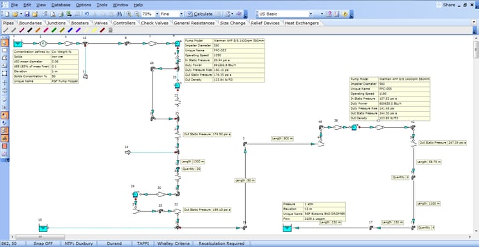
Figure 2.1: Mining Project Lifecycle.
3. Slurry Applications
Slurries appear in many applications throughout the mining and mineral processing industry and include:
- Tailings pipelines.
- Concentrate pipelines.
- Hydro-transport of minerals (e.g. a coal pipeline).
- Flotation circuits.
The modelling of slurry flows is often a complex phenomenon and all available methods are based on empirical data. The ability of FluidFlow to model both non-Newtonian fluids and heterogeneous settling slurries allows the engineer to investigate how different slurry compositions will perform in a piping system. For example, the sensitivity to concentration or particle size distributions can be analysed.
FluidFlow can model both non-Newtonian slurries (usually fluids with particles sized less than 40 micron such as concentrates and tailings) and also heterogeneous settling slurries in the same system. This is an invaluable tool to allow the engineer to fully investigate the operational possibilities within the system being designed.
With the addition of the 4-component model, FluidFlow can uniquely model slurries that contain both a homogeneous component and a heterogeneous settling component.
Case 1: Tailings Booster Pump Design (Heterogeneous Settling)
FluidFlow was recently used to size and select a booster pump to be installed in an existing tailings line. Tailings fluids often contain a large amount of fine particles and can be considered as Non-Newtonian fluids – i.e. the particles are homogeneously mixed with the carrier fluid to create a new fluid with specific rheological behaviour. However, in this case, the solid particles in the tailings were relatively coarse, with a d50 of 50 micron and d85 of 100 micron. This meant that the fluid was acting as a settling slurry and settling out was occurring in the pipeline.
The option of installing a booster pump in the existing line was investigated by using a FluidFlow model which was benchmarked against the existing system prior to the introduction of the new pump. This allowed the engineers to carefully size the pump and ensure that the new operating parameters of the system avoided particle settling.
The FluidFlow equipment database already contains pump performance data for most Warman AH series pumps. This allowed the engineers to quickly evaluate a range of pump models before arriving at the most suitable selection for the system. A Warman 10/8 AH pump model was selected for installation in this case. Figure 3.1 provides an overview of this system.
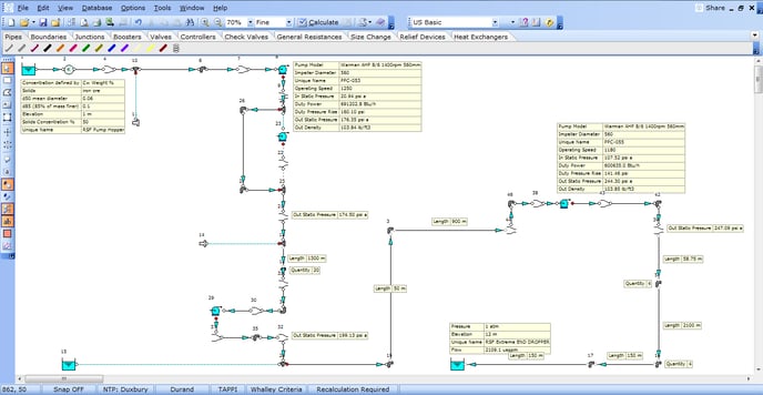
Figure 3.1: Slurry Pipeline Model.
The system curve for the pipeline (after the pump has been included) can be seen in Figure 3.2 and compared to the theoretical chart which indicates that the slurry is now operating in the heterogeneous zone. The results also indicate that the system is now operating above the calculated maximum deposition velocity, thus avoiding potential settling in the line.
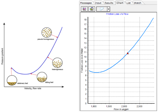
Figure 3.2: Theoretical graph vs FluidFlow output.
When modeling vendor pumps in FluidFlow, engineers can view the duty point on the performance curves. Figure 3.3 provides an illustration of the duty point for the new pump when operating at a speed of 1400 RPM. Note, FluidFlow allows you to model changes in pump speed and impeller diameter and study the effect on how a pump performs in the system.
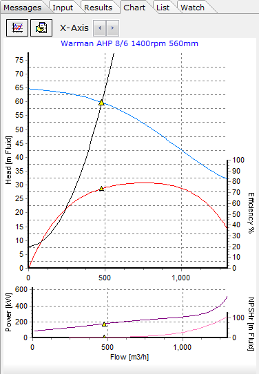
Figure 3.3: Pump Curve.
Case 2: Copper Concentrate Pipeline (Non-Newtonian, Non-Settling)
With the inclusion of databases on the software architecture, FluidFlow allows the engineer to create a new fluid and directly input the rheological data of a non-Newtonian slurry. The data can then be visualised, ensuring that the most appropriate non-Newtonian model is selected. Power law, Bingham Plastic, Herschel-Bulkley and Casson models are all available in FluidFlow.
Figure 3.4 provides an illustration of a copper concentrate which has been defined as a Bingham Plastic. Extrapolating the curve to the y-axis indicates that a yield stress exists and once this yield stress is surpassed, the fluid exhibits Newtonian behaviour, i.e. a constant viscosity.
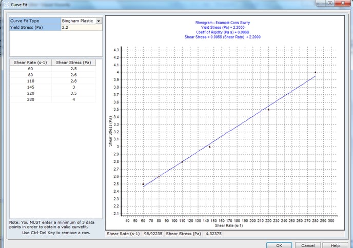
Figure 3.4: Direct rheology entry and model selection.
Once the fluid is defined in the database, FluidFlow will automatically apply the appropriate friction loss models to arrive at an accurate solution.
4. Process Applications
In addition to the slurry applications described in Section 3, FluidFlow can be used throughout the process side of a typical mining operation. In a mineral processing plant where services often follow the same route, FluidFlow becomes a valuable time saving tool due to its ability to model different fluids from the same environment so for example, a model that has been created to design a process water system can be used to design the instrument air system which runs along the same route, simply by changing the boundary conditions.
Some typical applications for FluidFlow in the mineral processing environment include:
- Flotation circuits (including launder flow and froth factor de-rating)
- Grinding circuits
- Thickening circuits
- Process water circuits
- Compressed air circuits (instrument and process)
- Dust suppression and extraction systems
- Pressure and Heap leach spray systems
- Magnetite recovery systems
- Dewatering circuits
- Heat exchange circuits
Case 1: Dust Extraction System
The model shown in Figure 4.1 was used to size the ducting and fan required to remove dust from the conveyor system taking ROM product from the primary underground crusher to the secondary crushing circuit hopper. The conveyors ran in tight tunnels and had hoods located over the centreline of the conveyors to remove dust at various points in the system.
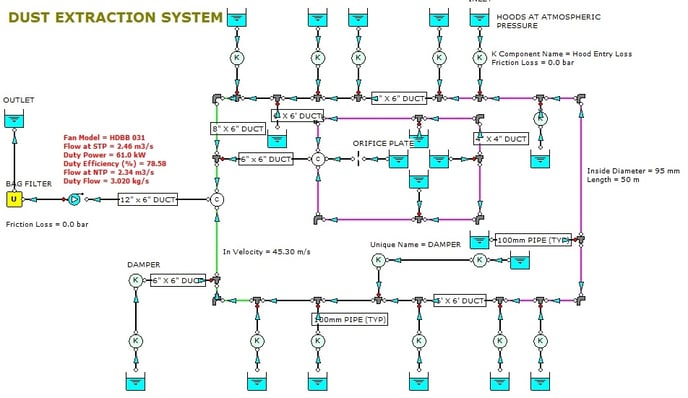
Figure 4.1: Dust Extraction System.
Case 2: Cooling Circuit
The model in Figure 4.2 shows a typical cooling circuit. FluidFlow offers the ability to accurately model heat transfer through exchangers, and also calculate heat loss through the pipework including any insulation that may be present. In this way we can gain an understanding of the heat load required to maintain a certain temperature or alternatively, determine the resulting temperature for a given heat exchanger capacity.
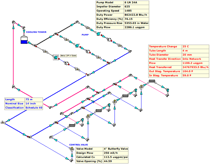
Figure 4.2: Cooling System.
In this model we can see normal operation using two duty and one standby pump arrangement. For the case depicted above, the standby pump, although present in the model, is turned off and hence produces no flow.
5. Mining Applications
Applications from a mining perspective include water distribution networks, water scavenging networks (e.g. bore pump systems) and mine dewatering systems.
Pit Dewatering
A model of a pit dewatering plant was developed for the site as shown in Figure 5.1.
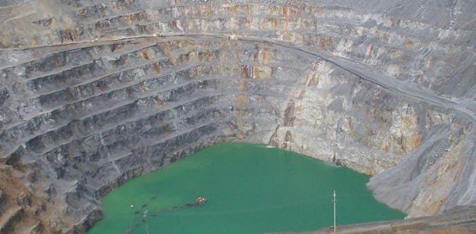
Figure 5.1: View of the disused pit and pontoon mounted pumps.
The model was used to design a dewatering system required to evacuate ground water accumulating in the bottom of the disused pit, and transport it overland to the process water pond.
The model consists of two parts; the initial lift along the pit incline to a holding pond, then a second portion which involves a long overland pipeline to the site of the existing process water pond. An overview of the initial lift can be seen in Figure 5.2 and the overland pipeline in Figure 5.3.
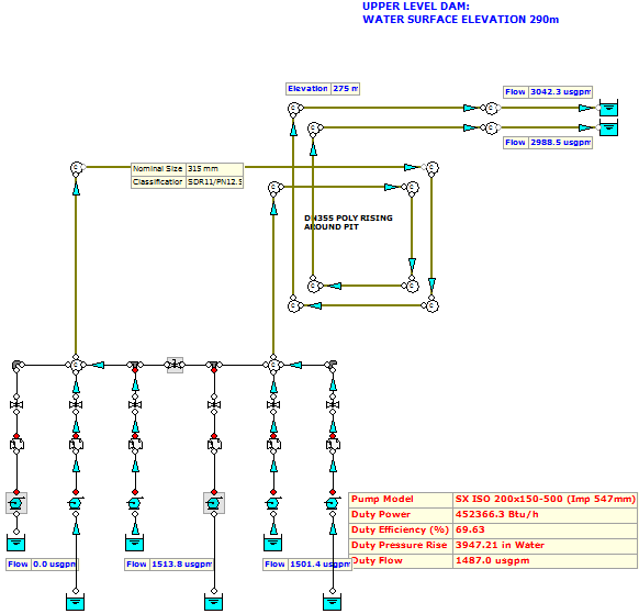
Figure 5.2: Model of Pit Lift.
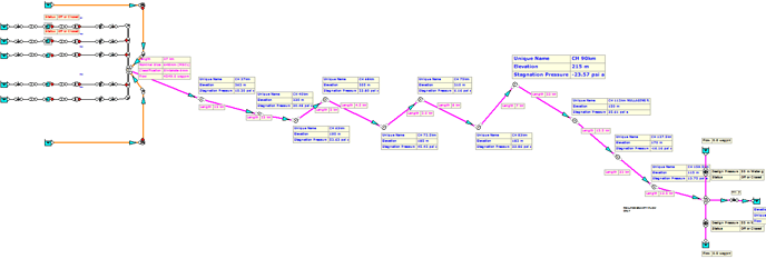
Figure 5.3: Overland Pipeline.
The areas of concern for this system were the avoidance of slack flow or cavitation in the downhill overland pipe run, and ensuring that the pontoon mounted diesel pumps in the pit had sufficient head to overcome the lift at sufficient flows. You can see from Figure 5.2 that 4 Southern Cross pumps were required to generate the required flows.
The ability to plot hydraulic and energy grade lines in FluidFlow allowed the design team to assess the overland portion of the system for cavitation and slack flow. Two cases are shown below; the system without cavitation is when the pump station is fully operational. The case which indicates slack flow is when the pumps are turned off, and gravitational flow is occurring.
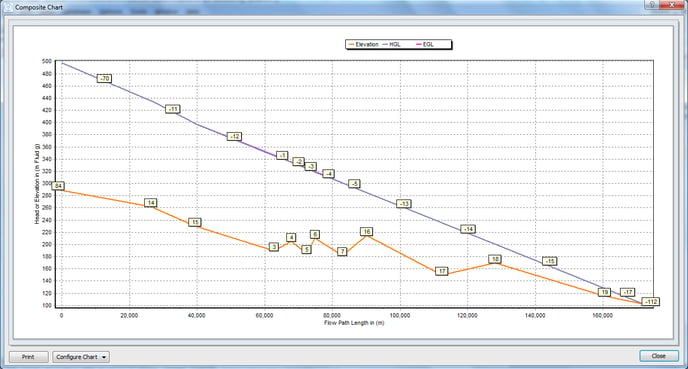
Figure 5.4: Pumps Operating.
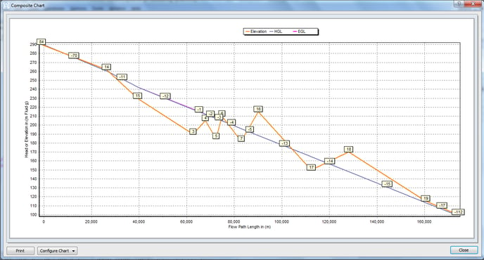
Figure 5.5: Gravity Flow, Showing Grade Line Falling Below the Pipe Elevation.
In this case, the model was used to successfully size a pressure sustaining valve at the end of the line to maintain positive pressure throughout the system, thus avoiding slack flow in the second case (Figure 5.5).
6. Conclusion
FluidFlow is a fully fledged piping system modelling package, an ideal tool for addressing the complex issues that arise when designing systems within the Mining and Mineral Processing industry.
The ability to model slurry systems with flexibility and accuracy is fundamental to successful designs, and FluidFlow has years of experience in this area. The software has been designed by engineers with a background in the Mining industry.
FluidFlow can be used at any stage of a capital project, and the effort put into maintaining an accurate model will also yield dividends when the plant is fully operational, and undergoing process improvements and modifications to the piping systems.
If you have a specific design application and wish to use an intuitive user friendly program to speed up your design process, contact us at: support@fluidflowinfo.com.
7. Testimonials
Testimonial 1:
“FluidFlow has been instrumental in designing pipeline systems for Lycopodium Minerals Canada. The training provided was succinct and effective in familiarizing the Engineers with the software. Well organized training literature and actual industrial systems solved during the course continue to benefit our engineering team.”
Zuned Shaikh, Mechanical Engineer, Lycopodium Minerals, Canada.

Testimonial 2:
“I have never regretted the decision to undertake FluidFlow onsite training. It was perfectly orchestrated with the right trainer and right audience. The content of the training covered all areas of our interest – the software is not used only for slurry piping (like it was done in the past) but also for all clear fluids and gases.”
Predrag Blagojevic, Manager, Mechanical Eng, Worley Parsons, Canada**.**

Testimonial 3:
“FluidFlow is fast, easy to use, accurate and a reliable package. The software drastically cuts design time - these benefits apply not only to the designer but also to the peer review team. During operation of the built systems, the agreement between running plant pressure readings against design data was highly accurate. That bought my full trust in the package”.
Mat Landowski, Lead Process Engineer
