FluidFlow does not include a specific damper node.
Users tend to use either of the following approaches:
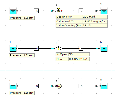
Option 1: Use a flow control valve node. This allows you to define the flow rate and the software will calculate the resultant % opening of the valve device for the given operating conditions defined. Note, the % opening is a function of the valve performance data defined in the database as well as the system operating conditions.
Option 2: Use a flow valve node (manual valve). This allows you to define the % opening of the valve device and the software will calculate the resultant pressure drop, flow rate etc for the given operating conditions defined. Note, the flow rate is a function of the valve performance data defined in the database as well as the system operating conditions.
Option 3: If you don't necessarily need to know the % opening data for the damper/device and this is something which can be established at commissioning stage, you can model the pressure loss across the damper using a Kv node or a Generic User Defined node etc. These nodes are available from the General Resistances tab of the Component Palette. You can also use a known flow boundary to define the flow rate through the damper.
The image below shows the three options.
